High Performance Motion Control
Content:
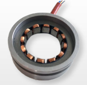
Rotary sensors are the key component to achieve best performance for demanding motion controls which require the best step response, high accuracy and high resolution without oscillations and ripple. Resolvers in particular are very robust sensors with infinite resolution. They allow keeping the electronics away from the “hot” area.
Absolute Angle
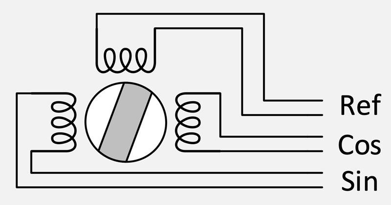
A single pole pair (p=1) resolver gives an absolute signal over 360° mechanical rotation. The electric zero (E.Z.) is defined as the unique angle for Usin=0 and Ucos = 1.
To measure the angle of a move it is necessary first to define the zero position of the machine. To adjust the E.Z. to the zero position of the machine, the resolver has to be rotated manually and blocked with the three griffons in the servo groove.
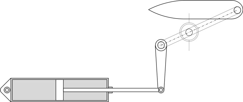
At power on the resolver gives the rotation angle of the rotor relative to the stator. The single speed resolver is the ideal sensor for measuring position of moves which do not exceed 360°. As a rudder control for example.
Multipole resolvers have many electrical zeros. There is an E.Z. for every pole pair. They give an absolute signal within an electrical period (360°/p). Multipole resolvers have a higher accuracy and resolution than single pole pair resolvers.
Resolution
Considering a resolver-RDC system. It is easy to analyse the performance . Resolvers are analogue sensors which require an RDC (Resolver Digital Converter) giving a speed and a position output.
An RDC is a chip containing an oscillator in the frequency range 1 to 10 kHz feeding the primary coil of the resolver and a converter calculating the arctangent of the angle from sine and cosine signals coming from the resolver.
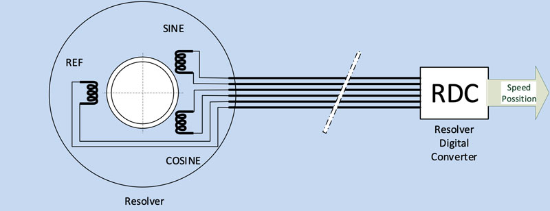
The RDC converts the angle of an electrical period into 10, 12, 14, 16 bits or more.
The resolution for 1 mechanical turn is the product of number of pole pairs and the resolution of the RDC
R = Resolution
p = Number of pole pairs
RRDC = RDC Resolution
R = p * RRDC
Resolution means that this is the number of steps or increments the system gives for 1 mechanical revolution.
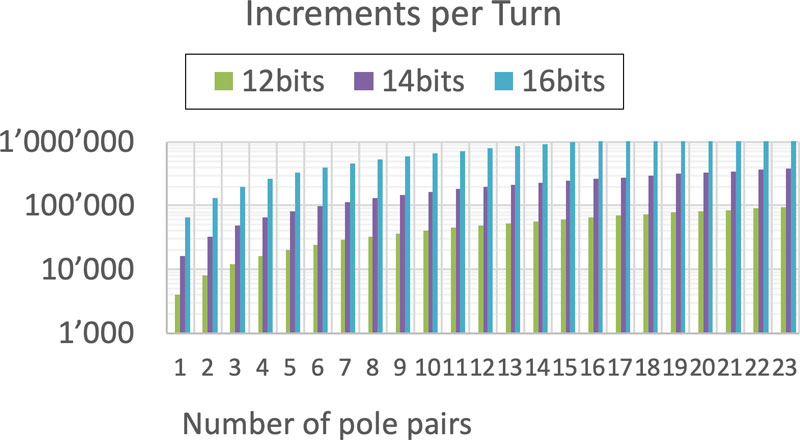
This shows an extreme high number of steps per turn which gives a broad choice
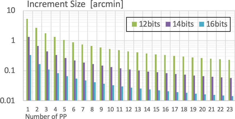
Increment
An increment is the length of 1 step.
I = 360° / RRDC * p
As the resolution is very high, it is a good rule to choose an increment ten times smaller than the desired accuracy.
Accuracy
Position accuracy of a resolver RDC system depends essentially of the accuracy of the resolver. In fact, we have to add the error of the resolver to the error of the RDC:
- ε = Total Error
- ε RDC= Resolver Digital Converter Error
- ε R= Resolver Error
p = number of pole pairs
ε = εR + εRDC / p
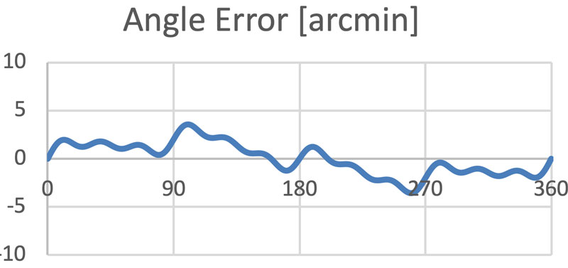
The higher the number of pole pairs the lower the total error of the resolver-RDC system.
Typical angular error curve of a resolver:
εR (ϕ)
Resolver angular error:
ϕR = ϕ + εR
Slope of the resolver error curve:
dεR/dϕ
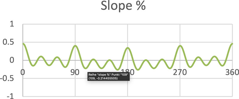
Resolver speed error:
dϕR/dt = ω(1+dεR/dϕ)
In other terms a rotor eccentricity gives typically a harmonic 1 error. If an eccentricity of 0.1 mm produces for a given resolver an angle error of 30 arcmin the max slope will be 1 %. This is a harmless example. Errors with higher harmonics (e.g. H4, H12…) produce much higher slopes. So, it’s important for high speed applications to select a resolver with a low speed error and to avoid any disturbances on the resolver lines.
While the angular error affects the position accuracy of the motion, the speed error limits the gain of the velocity loop which is important for the performance of motion control.
Electric Motor Commutation
Brushless synchronous motors or servomotors needs to synchronize the turning magnetic field with the rotor. Generally, one single resolver is used for three functions.
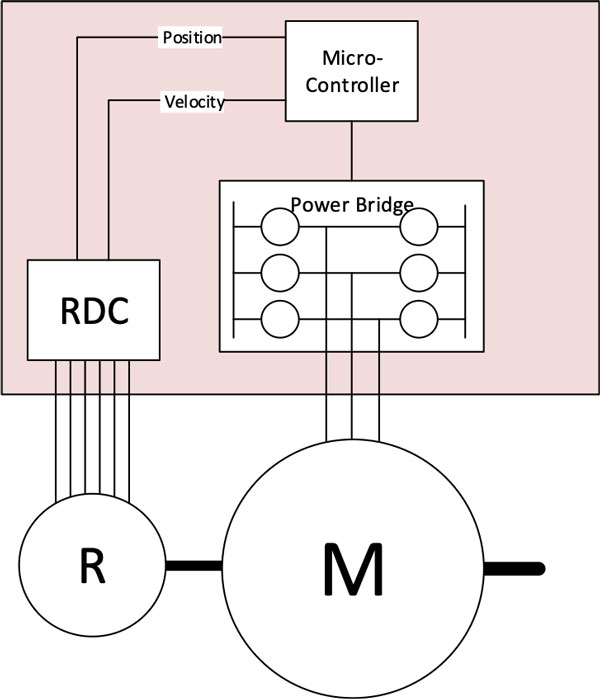
- sensor for commutation
- sensor for speed loop
- sensor for position loop
For commutation, single pole as well as multipole resolvers are used.
Another solution is to use the E.Z. of a speed 1 resolver.
If the number of pole pairs of the resolver is identical to that of the motor, the drive (also called homopolar drive) can start at power on without needing a zeroing routine.
In all other cases when a higher resolution or precision is required e.g. a zeroing routine is necessary.
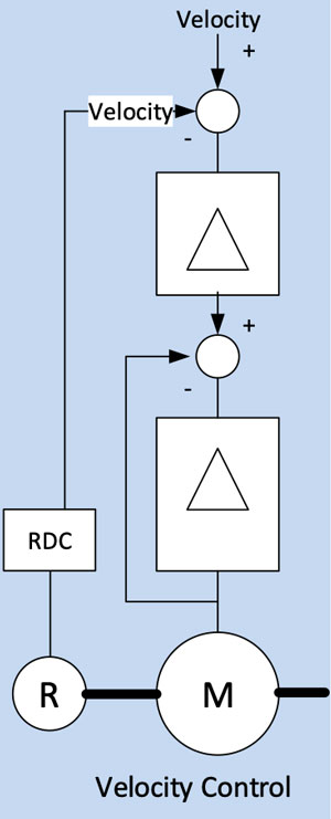
Speed Control
This block diagram shows a typical speed control. It’s easy to see that harmonic speed error directly effects the speed of the motor. The gain of the velocity controller at high speed is limited by the content of harmonics of the resolver signal. It gives the best performing velocity control. Speed control are used on E-mobility applications. It allows single pedal speed control: acceleration and deceleration with kinetic energy recuperation.
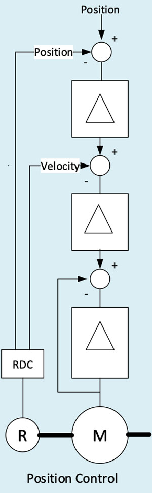
Position Control
The high resolution of a resolver-RDC systems allows very precise positioning of the driven mechanic.
A high velocity loop gain stabilizes the position loop. To achieve it at high speed, it is necessary to use resolvers with low speed error.
Positions controlled moves are used on machine tool, robots and precision actuators.
These application examples show how to implement resolvers in order to solve complex controlengineering problems. For more information please don’t hesitate to contact Admotec Precision AG.